The author describes below how to set up an efficient pit box for combat competition. Buzz is seen here using his pit box to prepare an 80mph combat plane for a match at the Fall Follies. Buzz won the contest. Flying Lines photo.
Several years ago, I wrote a brief article on things to consider when building a pit box. For many years, I have used the "Buzz Box." This was the second box that I built and served me well. Recently my car was broken into and the toolbox used for secondary tools and materials stolen. This along with changes to the events and new events that I fly made me look at my pit box. I wanted to add a power panel so I could use electric starters. When I looked at the "Buzz Box," I realized a power panel could not be retrofitted because the box is only four inches deep. Secondly, it needed to accommodate secondary tools. Time to build a new "Buzz Box."
The new "Buzz Box" needed to be 5 inches deep. The width needed to be one inch wider. The length would be the same. Time to go buy plywood.
The original was made from quarter inch mahogany plywood; the new one would be made from quarter inch Birch. A 4' x 8' sheet of Birch plywood cost $20. I had them rip two strips five inches in width and then cut the remaining in half. The lumber store had a precision table saw and the pieces would be exact. The cut in half of the remaining let me get it into the car. A word of caution, make sure the plywood is reasonably straight. The box could have been built with a 4' x 4' piece of wood. Some lumber stores will sell half a piece.
This is not meant to be a detailed how to article, but one that provides guidelines and techniques.
Cut the four sides.
Next, cut the opening for the power panel.
"Buzz Box" original was assembled using butt joints, nails, and epoxy. However, since I have a super duty router and router table I decided to route the edges. I pulled out a 1/8" router bit, set the height and depth, and passed a back and side through the router. Much to my surprise when I put the two pieces together, they did not fit properly. A trip to the radial arm saw and the edges were removed and the router adjusted. A pass through the router and the same results. This process went on for more time that I will admit to. The guys on DIY never have these problems. I got the mic out and checked the quarter inch (.25) plywood, which was .20. A readjustment of the router and I was in business. A new side piece and rear piece was cut and all the pieces routed.
What is needed are corner clamps. A trip to the hardware store produced two clamps. The ones shown in the pictures are Pony #9166, 90 degree, 3" opening and sell for around $8 each. They are very easy to use and a great addition to the tool collection. Time to assemble the sides.
I decided to use epoxy rather than wood glue. This meant waiting on glue to dry. Here you see the progression of assembly.
I decided to put the bottom inside the frame. I measured the frame and cut the bottom. A test fit and it worked. Before gluing the bottom in establish the center lines. Once this is done, glue in the bottom.
While the bottom is drying, cut the two main handle support and rear battery compartment cover.
Next, cut the two handle support pieces and the handle.
Cut out the front to rear stringer including holes to lighten the structure.
Make sure you dry fit all the pieces including the battery before assembling.
Once the bottom is dry, establish where the supports will go. This is based on keeping the battery in the center of the box and the width of your hand. The original "Buzz Box" handle was on the center (front to back) but slightly off center (left to right). The new version is centered. The front to back stringer and left handle support and are glued.
The left to right stringer is cut and a wire route hole drilled for the power panel to the battery.
Once the glue is dry from Step 6, the right hand handle support and left to right stringer installed. In the final stages, a second wire route hole was drilled.
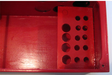
While Step 7 is drying, measure the blanks for top panels. Once the blanks are cut, it is time to layout the panels and cut the holes. Since this box will be used in competition, I wanted to make it easy for the pit crew to get at the equipment. When you look at a pitting situation during a combat match, you could be replacing a prop, a bladder, refueling the bladder, and replacing a plug. Some things I wanted to improve on from the original "Buzz Box" were the storage of props and bladders. Secondly was a location for a primer bottle. Thirdly were secondary tools, specifically reamers. In setting the hole diameters measure the props as well as the tools. Before drilling the cover, use a scrap piece of wood and drill test holes to make sure the diameters are correct. A series of drill bits including blade bits, Forstner, machine bits, and hole saw were used. A scroll saw is used for the fuel bottle hole.
There are three distinct panels. The first has fuel related components, which include the following:
Panel 1
Fuel Items
Propeller Items
On the same panel, are propeller related items, which include the following:
Propellers
The propeller holes are drilled to hold fast, F2d and 1/2-A props.
Cutting Tools
Also included on this panel are two cutting tools; a razor blade and a pair
of scissors.
Panel 2
This panel has nut drivers and pliers
Panel 3
This panel has tools for socket head cap screws and the glow plug caddy.
To attach the panels to the box, cut out stringers and use blind nuts to secure the panels.
The small dowel is used to keep the primer bottle and after engine run bottle at the correct heights.
Depending on your tools, you may need to add some supports to keep the tools from bouncing. Here is the underside of the panel that uses wood and rubber to hold the tools firm. Not shown is the underside of the nut drivers, which has a plate, which mirrors the holes in the top of the pane.
Finish
The original "Buzz Box" was finished with K&B epoxy. Over the life, it was refinished once. The new box was to be finished with System Three Resin with a color agent added. This is not a good time of the year to be using resin, it takes forever to dry. I tested the epoxy and on the bottom of the box and the bottom of the top pieces. I was not satisfied with the finish. This was sanded off and a search begun for an alternate material. I found this in Klass Kote. I spoke to them about the material and that I was looking for a product like the old K&B epoxy.
The finish was applied using Iwata airbrushes. If you do not have one of these, get one. These are a great tool.
The power panel comes with alligator clips for connecting to the battery. The battery charger is also fitted with alligator clips for connecting to the battery when charging. Alligator clips are not a good choice for connecting the panel to the battery. I removed these from the panel and replaced them with a terminal connector. I made up a set of connectors for the battery using blade connectors and terminal connectors. Next, I drilled two holes for terminal post (6-32 screws). When it comes time to replace the battery, all I have to do is open the box, remove blade connectors from battery, put in new battery, and replace the blade connectors.
Banana jacks are provided for connecting external devices. I removed the alligator clips from the charger and used one set of the banana jacks for the charger. When it comes time to charge the battery, these will be placed in the starter location.
I used banana-type test adapters (Radio Shack PN 274-0717) for the connector for the glow plug and the starter. These use a screw to hold the wire in place. I placed solder on the wire and then tightened the screw. I then heated the solder to create a button. I also put a drop of solder on the screw.
Pay close attention to the positive and negative side on the starter. I used a piece of red heat shrink to identify the positive side. You can also mark the negative side with a black permanent marker.
At the rear of the box, I glued on high strength magnets. These magnets came from Optiva tooth brushes. As you can see, it is holding a series of open and box end wrenches.
The yellow tool is a Bondhus hex wrench set. You can get these for around seven dollars and is an invaluable tool.
The Glow Plug caddy is attached. This one comes from MBS.
The open area needs to carry divided boxer for small parts.
The open area also needs to carry finger guard, glow plug clip, and other miscellaneous tools.
Conclusion
The new box weighs 20% more than the original. The bulk of the weight increase is the larger battery.
If you take on this project, figure it will take about 5 days to get the box built and ready for finishing. Cost will vary depending on what you are reusing. Aside from the cost of plywood, the paint was the most expensive part of the project. Primer, paint, and thinner were around $100. This will be used on other projects. The amount used for this project was around $25.
 Update, September 2009
After using the new Buzz Box for several contests this year, I have made a slight change. The panel that is used to hold props and bladders was not working the way I had planned. Bladders and the blow tube for clearing floods from F2D engines would slide out holes and under the panel.
To solve the problem, copy the hole pattern onto another piece of plywood. Make sure you account for the piece going inside and drill the holes out. Glue this piece approximately 2.5 inches below the top piece. Problem solved; bladders and blow tube now stay in place.
This page was upated Jan. 23, 2021