![]()
Scale Matters
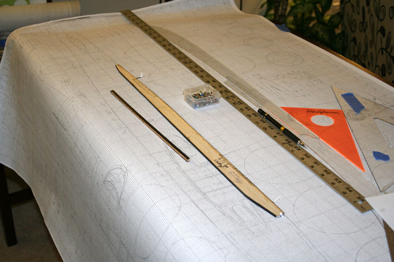
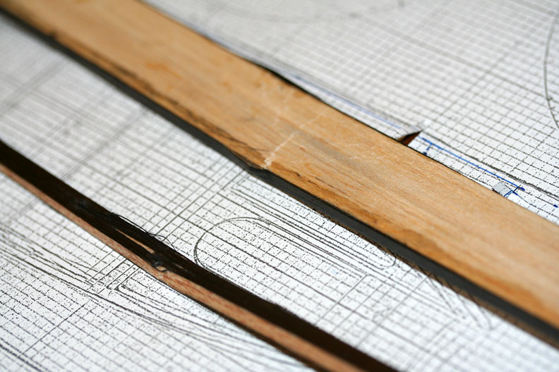
The longeron and stringer on the workbench ready for testing. All photos by Orin Humphries.
I-beam ultimate strength tests
By Orin Humphries
November 2014
The generic I-beam shown in the last installment successfully withstood a 10-pound load in bending, which I thought was satisfying for a 3/16” square balsa stringer(with carbon fiber strips). It did leave me wondering what its ultimate strength would be. Some thought produced the simple test set up that you see in the photos.
Background
First, though, I'll give a little background into why this subject. My current project is the straight-winged F-84 Thunderjet at 10% over 1/12 scale (to get my wing loading down). My next project will be a Super Corsair. The next one after the Corsair will really need efficient beams in its wings; weight would be poison to it. My F-84, then, is really the test bed for many technologies and features of that later project, including the internal style of Fowler flaps that it will use. Thus, I am prototyping things in the Thunderjet.
My F-84 is unusually challenging for me due to the number of working features I have chosen to install in it. One of the reasons for this complexity is my need to have a real challenge to keep my brain cell “a-sparkin'." Another reason is that once I became good at flying my A-26 that you may remember, it was a boring airplane for me. It had no working features in the air. If I would have had just one airborne scale function, I would have won the 1989 Nats in Richland. I took second by 1.5% of the score.
My F-84, now, has six major holes in the fuselage for features, not counting the air intake and exhaust orifices. The holes are for the cockpit, of course, the nose gear well, the nose gun bay, the radio compartment, speed brake, and servo access.
Beam Design
Beams, by way of review, are usually meant to be strong in one bending mode and not so much in other bending modes. Those situations are taken care of by other structural members. When an I-beam bends, the chord on the outside of the curve is stretched, so it is in tension. The chord on the inside of the bend is getting squeezed so it is subjected to compression. Together the chords form what we call a “tension-compression pair.”
A basic principle of structures is that they are strong so long as they can retain their designed shape. When things get out of that shape, they fail. The failure mode for I-beams is often the buckling of the compression chord. To counter that tendency, the proper design guideline is to have three times the strength in the compression chord that you have in the tension chord. Tension by its nature tends to keep things in their unloaded shape so you don't need special consideration there. Putting three times the tension strength into the compression chord usually requires using up some space around it that could be used for other purposes like fuel storage in 1:1 scale birds. We in modeling don't have the luxury of extra space. Fortunately, Mother Nature has given us something very useful.
 The strength of woods is linearly determined by their weight, across the many species of common wood types. Now, spruce is three times as heavy as balsa, all other things like dimensions being equal. That means that a 1/8” sq. spruce stringer is generally three times as strong as a 1/8” sq. balsa stringer. We have the recommended strength increase occurring within the same space.
My F-84's wing beams, spars, in our lingo, have to support the main landing gear loads. I used 1/64 plywood for the webs and glued 1/8 sq. stringers to either side at both the top and bottom of the web, thus forming an I-beam.
The spruce chords above are in compression from landing gear loads and the balsa chords are in tension from them. In my F-84's beams, once they are out beyond the landing gear mounts, the upper chords revert to balsa like the lower chords. I put in strength only where I need it.
Tests
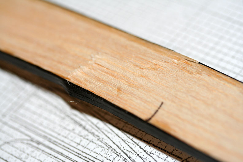
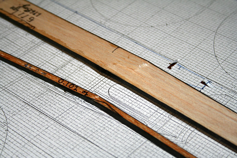
Let me record the details of the test specimens for the record. The 3/16”sq. stringer with.007” t. carbon fiber (CF) straps for beam chords weighs 0.102 oz. and is 10 11/16” long. Both chords are .007” t. CF. This equal thickness of the chords was a construction flaw not addressed here for just a screening test. The longeron specimen is in the newly arrived at design shape and thickness for my side longerons. It is 1/8” t. balsa, it is 15/16” wide, is 22” long, and is 8.77 lbs./cu.ft. balsa stock. The longeron weighs 1.168oz. For the longeron I partially met design recommendations by adding a second layer of CF strip to the compression chord. That chord was, then, .014” t. When I added the CF strips to the balsa specimen, I found it best to put on maybe a 7” bead of medium thickness CA glue and stick the strip down sequentially. Trying to put the glue on the whole length and stick it all down at once was miserable!

Orin tests the strength of the longeron (left) and the stringer.
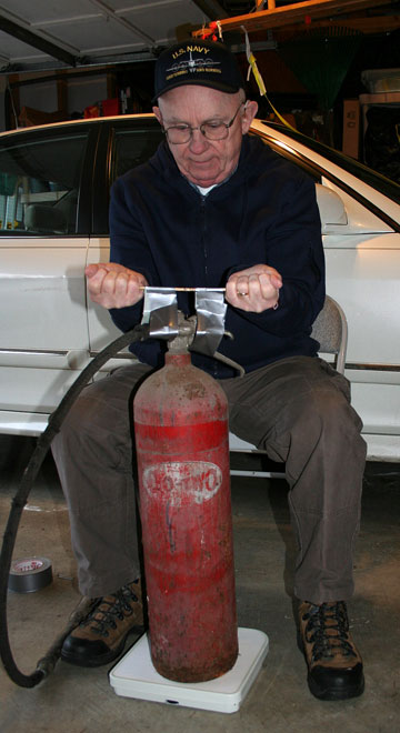
In my test rig, the load is furnished by a fire extinguisher weighing 47 lbs. It is set upon our bathroom scales. The fire extinguisher is suspended from the beam specimen with plain old duct tape. I read the scale as I lifted the specimen and noted the reading when the specimen broke. Subtraction gave me the ultimate load at failure. I supported the longeron at the locations of my hands during a real pull test of the actual fuselage.
I knew I would have a problem in testing the longeron to ultimate. It would want to flop over toward its side and fail in an off-axis mode, like a broad U-shape. I tried my best to keep the longeron vertical, but at one point the specimen got away from me and bent to the side. It failed, then, lower than it would have, at 29 pounds. That is still pretty good for a balsawood beam 1/8” thick.
This lower than desired load is not a total loss, however, for two reasons. The longeron specimen did not faithfully reproduce the longeron installation in the fuselage. In the fuselage, the longeron will be glued to the upper wing skin, which will resist flopping over and failing in that mode. Further, there are beau coup fuselage frames to keep the longeron in its designed shape. This 29# number is by itself much of the pull test, and there will be two other, smaller longerons, the upper and lower ones (this is the middle one at waterline 0.0), plus numerous skin stringers at the scale locations of every 15° around the frames. The skin also will contribute resistance to the pull test loads. This number, then, is more than sufficient. My structure even with the big holes here and there will survive pull testing.
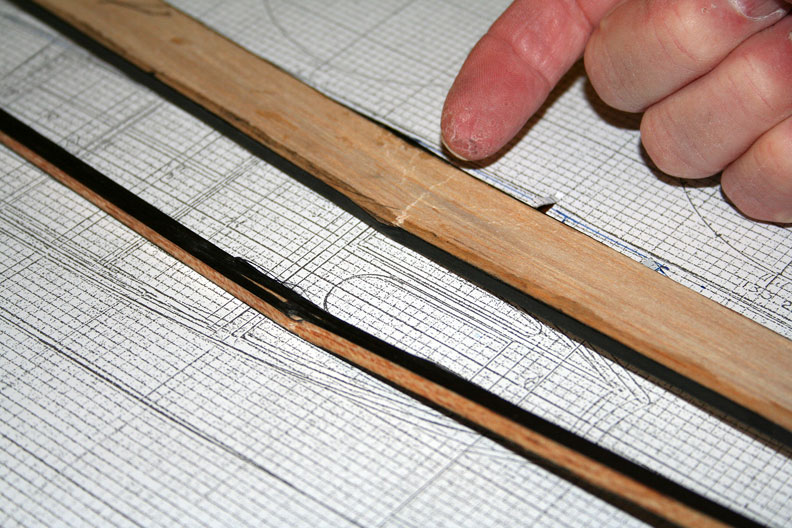
The big surprise was the strength of the 3/16 sq. beam! This is the same one you saw in the previous article. That little dude failed way up at 39#! Being square, it had little tendency to flop over toward its side like the longeron did. It failed in the compression member through delaminations as expected.
In my F-84, after these tests, my upper and lower longerons will be 1/8 sq. stringers possibly made from spruce. A way to build curving stringers in some other project with CF strips for their tension-compression pairs could be as follows. The CF reinforcing will end outside of the pull test support areas. I would add the CF strips by building up the longerons/stringers in place. That is, I would lay the inner CF strip into the notches in the frames first, and then put medium thickness CA glue on the strip. The balsa stringer will be laid in upon that, bent to shape as you go. I would add CA glue to the outer surface of the stringer and finally lay on the outer CF strip. That way I could build the longerons in the shape they must have without later having to bend them into place, causing internal stresses.
Well, that's enough sparking for my old brain cell for now. Happy flying!
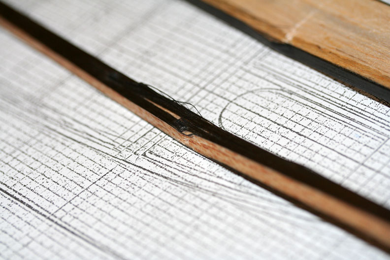
Photos below show various stages of construction of the longeron and stringer.
Flying Lines home page
Back to Scale Matters column main page
Back to Scale main page
This page was upated Nov. 22, 2014